Designed by Jon Idestam-Almquist
From "Radio & Television" April, 1961
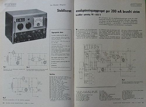
Anode voltage: 90-450 V max 200 mA in two ranges
0-100 V negative 5 mA
6,3 V 5 A with centertap
6,3 V 5 A with centertap
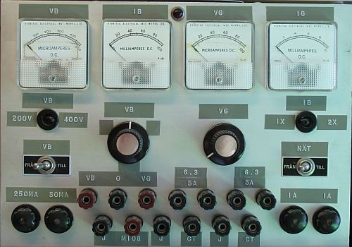
I built my unit a little different than was described. Four meters instead of one switchable.
(Click to enlarge)
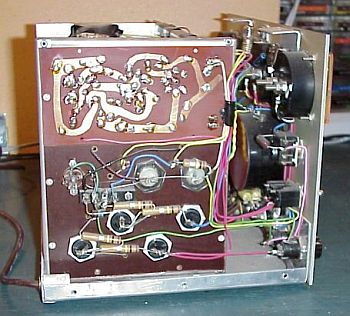
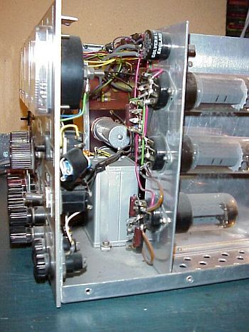
I made some pcbs the old fashioned way. Here is the left side where the PCB holds the two ECC83 and the 85A2.
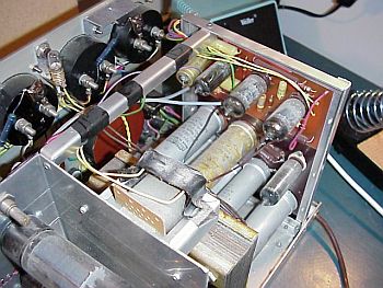
From the rear.
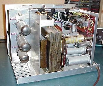
The right side with the connections to the EL34s and the GZ34.
C1, 2, 5 = 100uF 450 V insulated electrolytic cap.
C3, 4, 6 = 32 uF 450 V
C7 = 0,1 uF 250 V
C8, 9 = 10 nF 400 V polyester
C10 = 0,2 uF 350 V
C11 = 6,8 uF
C12 = 0,1 uF 600 V
C13 = 8 uF 500 V electrolytic
R1-2 = 82 ohm 5,5 W wire wound
R3-6 = 100 k 2W
R7 = 1,8 k 5,5W wire wound
R8-9 = 270 ohm 0,5W
R10-11 = 3,9 k 0,5W
R12-13 = 1,5 M 0,5W
R14 = 240 k 0,5W
R15-16 = 9,1 k 0,5W
R17 = 150 k 1 W
R18 = 25 k 1 W wire wound pot.
R19 = 100 k 1 W
R20, 21, 23 = 220 k 0,5W
R22 = 120 k 0,5W
R24 = 47 k 0,5W
R25 = 22 k 10 W wire wound
R26 = 5,6 k 10 W adjustable
R27 = 20 k 12 W wire wound pot.
R28 = 8,2 k 5,5W wire wound
R29 = 20 k 4W wire wound pot.
Sr1,2 = 1A fuse (at 230V)
Sr3 = 200 mA fuse
Sr4 = 20 mA fuse
V1 = GZ34
V2 = EL34
V3 = EL34
V4 = ECC83
V5 = ECC83
VR1 = 108C1/0B2
VR2 = 85A2
D1 = E250C50 (can be replaced by 1N4007)
Dr1 = 50 H 40 mA choke
Tr1 = Prim: 230 V
Sec: 2x450V/225 mA with tap at 250 V
2x3,15 V/4A
2x3,15 V/5A
2x3,15 V/5A
5V/2A