
Designed by my late friend Jon Idestam-Almquist
(May 6, 1928 - Jan 23, 2022)
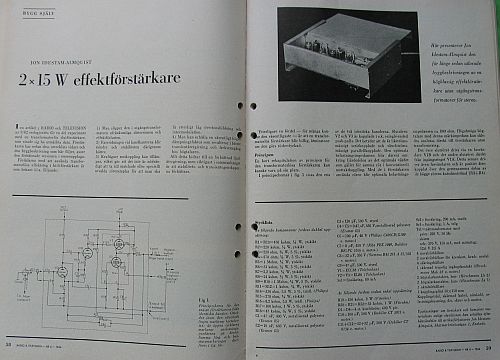
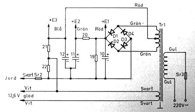
From an article in the Swedish magazine "Radio & Television" April, 1964.
With kind permission by Jon I have the priviliege to present not only the complete description for building the amplifier but also an earlier article that more deeply presents the construction.
You will find these links at the bottom of this page.
IMPORTANT NOTE:
All material on this site is Copyrigt Jon Idestam-Almquist.
You are only allowed to use the information for your own private purpose.
You may not copy any pictures for use on your own site without permission.
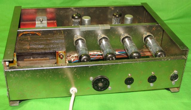
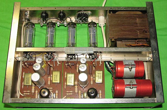
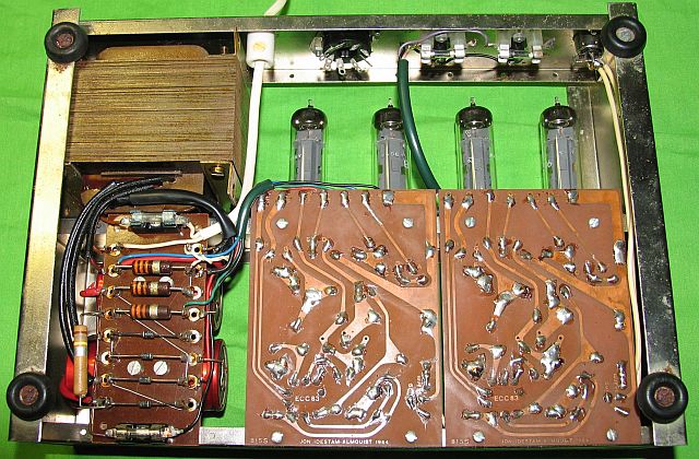
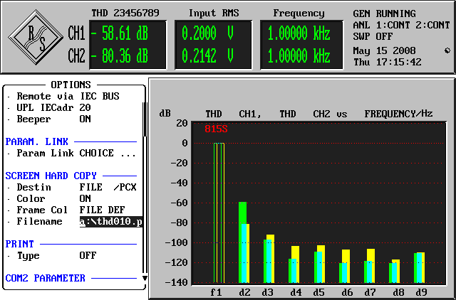
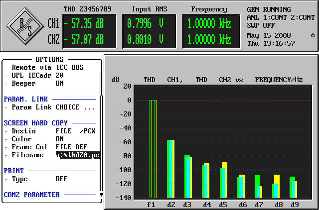
THD at 0,5 W before replacing the ECC83s.
L = -58 dB = 0,126 %
R = -80 dB = 0,01 %
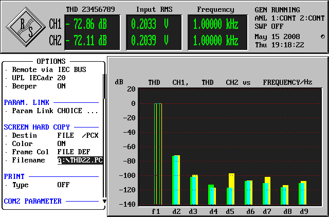
-72 dB = 0,025 %
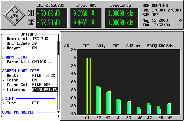
L = -71 dB = 0,028 %
R = -73 dB = 0,022 %
-57 dB = 0,14 %
-54 dB = 0,20 %
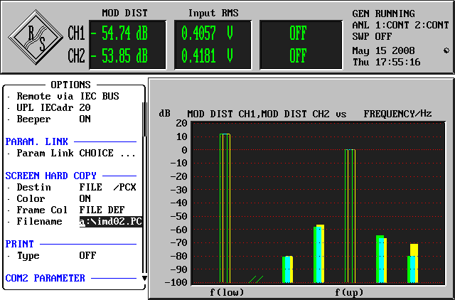
Here is a summary of my test. The reason for different output levels on the channels is that the gain was not the same on both channels. An asterisk * means that the signal was clipped . I did not test the tubes for conductance or anode current.
THD measured with 1 kHz
IMD measured with 60 Hz and 8 kHz 4:1
DFD measured with 10 and 11 kHz
|
Amp 1 before changing ECC83s |
Amp 1 after changing ECC83s |
Amp 2 |
Amp 3 Tested above |
||||||
| THD | L | R | L | R | L | R | L | R | |
| 0,5 W | 20 V | -58 dB | -80 dB | -73 dB | - 74 dB | -73 dB | - 72 dB | -78 dB | -79 dB |
| 2 W | 40 V | -52 dB | -73 dB | -65 dB | -67 dB | -66 dB | -66 dB | -70 dB | -73 dB |
| 8 W | 80 V | -43 dB | -58 dB | -60 dB | -58 dB | -58 dB | -61 dB | -65 dB | |
| 9 W | 85 V | -64 dB | clipped | clipped | |||||
| 13,8 W | 105 V | -35 dB* | |||||||
| 15,1 W | 110 V | -45 dB* | -50 dB* | -48 dB* | -48 dB* | ||||
| 18 W | 120V | -56 dB* | |||||||
| IMD | |||||||||
| 0,5 W | 20 V | -47 dB | -65 dB | -60 dB | -60 dB | -60 dB | -60 dB | -62 dB | -61 dB |
| 1,5 W | 35 V | -41 dB | |||||||
| 2 W | 40 V | -58 dB | -52 dB | -54 dB | -53 dB | -53 dB | -54 dB | -54 dB | |
| 4,5 W | 60 V | -47 dB | -49 dB | ||||||
| 5,3 W | 65 V | -48 dB | -48 dB | ||||||
| 7 W | 75 V | -41 dB | -45 dB | ||||||
| 8 W | 80 V | -57 dB | -57 dB | ||||||
| 10 W | 90 V | -30 dB | -47 dB | -42 dB | -45 dB | -41 dB* | -41 dB* | ||
| DFD | |||||||||
| 0,5 W | 20 V | -60 dB | -77 dB | - 75 dB | -75 dB | ||||
| 2 W | 40 V | -70 dB | -71 dB | ||||||
| 3,8 W | 55 V | -54 dB | -70 dB | ||||||
| 5,3 W | 65 V | -64 dB | -64 dB | ||||||
| 8 W | 80 V | -45 dB | |||||||
| 10 W | 90 V | -65 dB | |||||||
| Tubes | |||||||||
| ECC83 | Philips | other Philips | One Philips One Telefunken |
Siemens | |||||
| EL86 | Telefunken | Telefunken | Telefunken | EI | |||||
Test values will probably be much better with new Telefunken tubes, which I did not have.
Click on each picture to get a full size jpg approx 1240 * 1754 pixles
Be aware of that the text is in Swedish
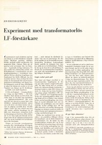 Page 48 |
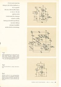 Page 49 |
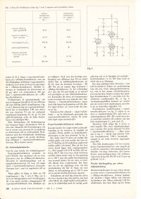 Page 50 |
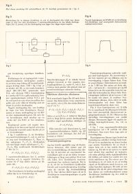 Page 51 |
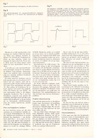 Page 52 |
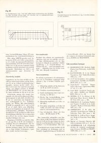 Page 53 |
Article from April 1964: |
||
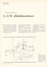 Page 58 |
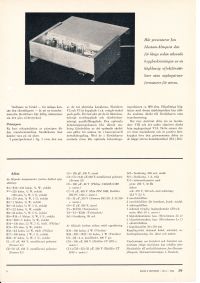 Page 59 |
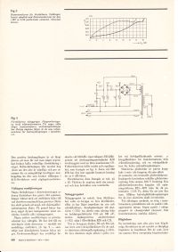 Page 60 |
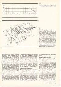 Page 61 |
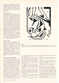 Page 62 |
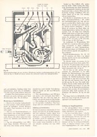 Page 63 |
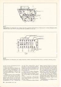 Page 64 |
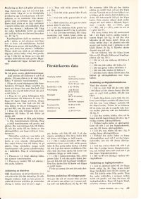 Page 65 |
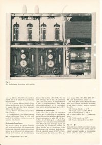 Page 66 |
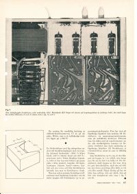 Page 67 |
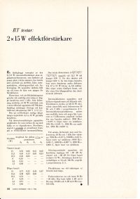 Page 68 |
|