A description in English how the XM1000 works.
This translation is not completely verbatim. If you know the German language, you also know there are grammatical constructions which would make the English version irritating and difficult to read (or plain wrong, grammatically speaking ;-) ) if translated literally.
I'll stick to the term Wehnelt cylinder (named after its German inventor Wehnelt, pronounced "*Vay*nellt") for the brightness control grid of a CRT (which is, to my knowledge, always a solid cylinder, prism or similar hollow shape, with the beam going parallel to the walls, never a wire wound/mesh grid transverse to the beam) because it is IMHO easier to remember than a "g" with an index number.
Overview:
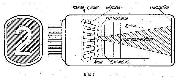
Heizfäden : filaments
Rechteckblende : rectangular aperture mask
Symbolblende : symbol mask
Leuchtschirm : fluorescent screen
Elektronenstrahlbündel : electron beam
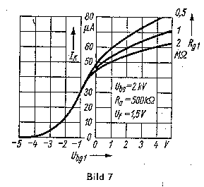
On one hand, the numeric display tube XM 1000 requires a relatively high anode voltage (2 - 3 kV), on the other hand, the numerals can be enabled with bias voltages below 10 V and reliably blanked with voltages around -6 V.
In order to achieve the display of multiple-digit numbers, the display tubes associated with
different digits can be driven using the time- multiplex method with high switching frequencies.
There is no danger of shortening the lifespan of the fluorescent material due to the higher EHT necessary for pulsed operation: Given a higher EHT, the electrons will penetrate deeper into the luminous layer, stimulating a greater share of the material into fluorescence. This means that, given the same beam current, the stress on the phosphor is lowered.
Construction scheme of the tube system
The right hand side of fig. 1 shows six of the twelve Wehnelt cylinders arranged in two columns of six each, which comprise the control electrodes and, together with their associated filament sections, anode sections and masks, form the cathode ray systems. There is one filament per column. Each of these systems is associated with a numeral shape (or a small hole for the decimal points) cut into the symbol mask.
If one of the cathode ray systems is enabled by applying an appropriate biasing voltage (with respect to the cathode) to the Wehnelt cylinder, an electron beam is emitted from there. The portion of the beam which is to illuminate the numeral or decimal point passes the shaped cutaway associated to this particular beam in the symbol mask.
>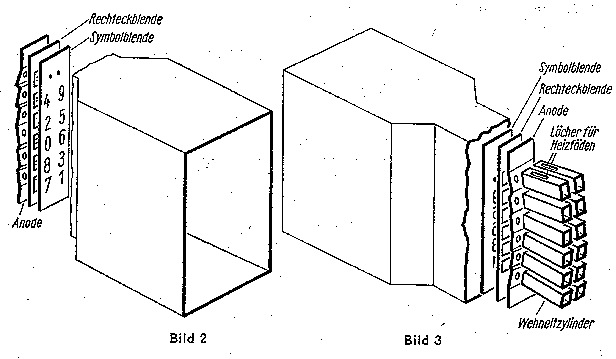
Figures 2 and 3 show the construction of the systems somewhat more detailed.
Löcher für Heizfäden: Holes for filaments
The oblong holes provided for both of the filaments passing through the Wehnelt cylinders are visible
in figure 3.
The beam, emerging from the directly heated cathode, is first influenced by the focusing and accelerating
effects of the field between the Wehnelt cylinder and the Anode, then passes another electrode with rectangular
apertures which is situated in the fieldless space before the proper symbol mask.

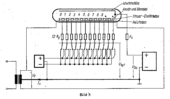
The cathodes are heated directly. The filament current source is center-tapped. EHT and control voltages are measured against the center tap potential. In the EHT line is a resistor of ca. 500 k Ohms, while each Wehnelt cylinder line contains a 1 Meg Ohms series resistor.
Steuer-Elektroden : control electrodes
Blenden : here: shaped electrodes (literally, the apertures or irises in a camera, blinds)
The control voltage source is connected to the center tap in a way that, depending on the position of the switches in fig. 5, either the enabling voltage of around 4 V or the blanking voltage is applied to the Wehnelt cylinders.
Heizleistung : heating power
Kathodenstrom : cathode current
Leuchtdichte : luminous density
jeweilige Leuchtdichte -- Leuchtdichte zu 0,18W : luminous density compared to lum. dens. at 180 mW heating power
In practical applications, electronic switches (usually transistors) will preferably be used
instead of the switches shown in fig. 5.
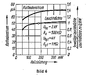
The heating system of the display tube is operated at 1.5 Volts with a current of 120 mA, resulting
in a total heating power of 180 mW. As can be seen in fig. 6, the heating power is dimensioned in a
way that deviations from its specified value have little effect on the cathode current and thus on
the luminous density.
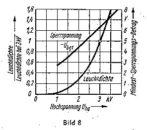
Using a relative scale of luminous density, figure 8 shows the considerable increase in luminous density
with rising EHT voltage and also shows that the minimum negative voltage required for cutting off the cathode
current (and thus blanking the digit) is dependent on the EHT voltage in a near-linear fashion.